Insert Rectangle/Line/Layer
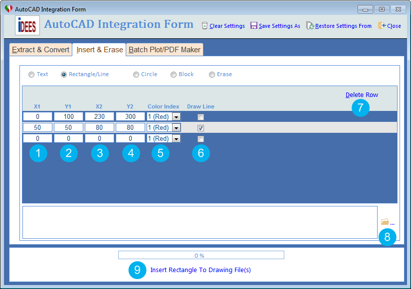
The second tool is for inserting Rectangle/Line. By this tool, in addition to being able to insert any rectangle anywhere in the drawing, you can also insert the line at the specified points by ticking on 'Draw Line' . All data in this form is based on AutoCAD data.
User must note that when he/she change anything in first row, another row will be appeared automatically and logically there is no limit to insert rows here.
The following snapshot show this tool:
To use each of these tools, firstly iDEES tries to open currently installed AutoCAD application in the machine and then start to draw related objects, so
Do not close the AutoCAD application at all until it's completely finished.
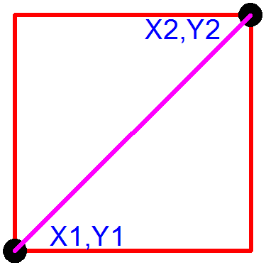
Shape of Rectangle & Line and location of points
1 |
The X position of insertion point 1 of the text. |
2 |
The Y position of insertion point 1 of the text. |
3 |
The X position of insertion point 2 of the text. |
4 |
The Y position of insertion point 2 of the text. |
5 |
Here user can select the color index for the text. This index is based of AutoCAD Color Index. |
6 |
By this option, iDEES draw a line between point 1 to 2 instead of drawing rectangle. |
7 |
If user need to delete any row from the list of inserted text, he/she must stay on that text and click this key. Please note that this deletion is done without any confirmation. |
8 |
By this browse key, user can select multiple AutoCAD files with certain type *.dwg or *.dxf |
9 |
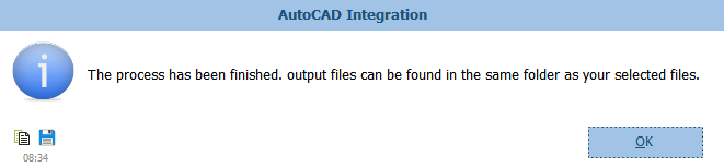
After all selection and settings, user should use this key to run the program. After successful running of the iDEES, the following message will be shown and then iDEES opens the related folder automatically:
|
Created with the Personal Edition of HelpNDoc: Free HTML Help documentation generator