AVEVA Configuration
AVEVA Configuration form is the first step to connect to AVEVA PDMS/E3D. In this form, user can set all required configurations for PDSM/E3D.
In this form user can create unlimited number of profiles. Profiles contain all configurations in the form and they can be related to different PDMS/E3D projects or in one project for different MDB or USER. Just one profile can be active anytime and all other tool in this category, just for with the configurations in the Active Profile.
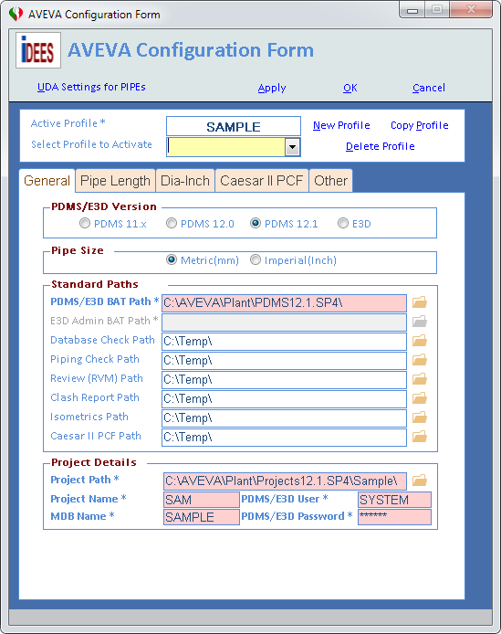
The following snapshots show all tabs of this form:


Now all parts of above form will be detailed here:

1 |
Shows the current active profile. This profile will be used in all facilities which are run here in after in the AVEVA Integration. |
2 |
Create a new blank profile. |
3 |
Copy the current profile with same name and configuration and then user can change some data. |
4 |
Delete current profile permanently and can not be undone. |
5 |
From this drop-down user can select any profile listed there and then press the Apply button at the bottom of form to make a current profile as Active Profile. |
Standard Paths:

PDMS/E3D EXE Path * |
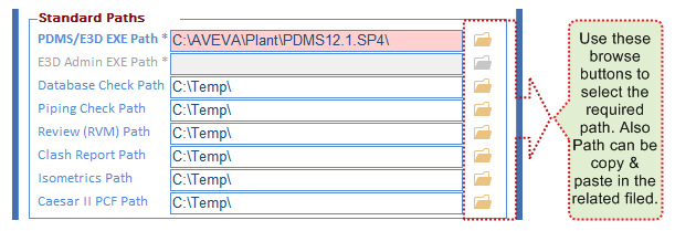
The installed path of AVEVA PDMS/E3D in the current machine(Not in the Server). Normally in a company all software install in same way with same path on all machines. But if this not followed in a company in each machine this path must be re-selected or the better way is to create profile for each machine. |
E3D Admin EXE Path * |
The installed path of AVEVA Administration in E3D product in the current machine. This is just enabled when in the PDMS/E3D Version Section, E3D 2.1 has been selected as follows:
|
When user uses Database check (DICE) facility, the results will be generated in this address. |
|
Piping Check Path |
When user uses Piping Design Check facility, the results will be generated in this address. |
When user uses Review File Creation (NAVIS) facility, the results will be generated in this address. This facility works manually and automatically, so when it works manually, user can select which path will be used for RVM file but in the automatic way, iDEES use just the path stated here in the 'AVEVA Configuration Form'. |
|
Clash Report Path |
When user uses Piping Clash Check facility, the results will be generated in this address. |
When user uses Isometric Facility facility, the results will be generated in this address. |
|
When user uses Export AVEVA To CAESAR II facility, the results will be generated in this address. |
Project Details:

Project Path * |
The path of the project where the main folder of the project exist. The main folder is a folder with name like ABC000 that ABC is the name of the project. |
Project Name * |
The name of the project must be entered here. Usually the name of the project contain 3 character like ABC or SAM. |
MDB Name * |
The MDB name of the project must be entered here. This is same as MDB name that user selects when he/she wants to login normally in the PDMS/E3D itself. |
The PDMS/E3D User name must be entered here. This is same as User name that user entered when he/she wants to login normally in the PDMS/E3D itself. (for some facility in 'AVEVA Integration', Free user of PDMS/E3D is required for example Database check (DICE) , ... ) |
|
PDMS/E3D Password * |
The PDMS/E3D Password must be entered here. This is same as Password that user entered when he/she wants to login normally in the PDMS/E3D itself. |
PDMS/E3D Version:

'AVEVA Integration' works with all available versions of PDMS and E3D until now (2017), so for each version which is used currently by the Active Profile, the version must be set in this section (PDMS 11.x includes PDMS 11.4 & 11.5 & 11.6)
Other Details:

RVM Template File |
When user wants to use Review File Creation (NAVIS) facility, he/she must prepare a template file in PDMS/E3D. The procedure to generate this kind of file is can be seen here. After preparing this file, the full path of that must be addressed in this field or beside Browse button must be used to locate this file. |
When user wants to use Isometric Facility facility, he/she must prepare an Option file in PDMS/E3D or he/she can uses default option files which are delivered by PDMS/E3D. After preparing this file, the full path of that must be addressed in this field or beside Browse button must be used to locate this file. |
|
UDA for Item Code |
In so many reports which are generated by this facility, there is column for Item Code (Identity Code or Commodity Code or something like that). Usually in PDMS/E3D this kind of code must be specified as UDA (User Defined Attribute) of SPCO (Spec Component), so if user like to see this code in his/her report, must type the full name( Including : in front of it) that UDA in this field like :ItemCode If this filed has not been set, iDEES uses 'Name of SPREF' by default. |
In the Support MTO facility and also some other reports, there is column for Support Tag. Usually in PDMS/E3D supports on pipes create as ATTACHMENT elements and as per Piping Standard Support document(or something like that) all supports must have a Tag. So usually in PDMS/E3D an attribute of ATTACHMENT like 'STEX' can be used to fill up as the support Tag. So user must put in this filed the name of that attribute like 'STEX' or 'SPLN' or 'SPLT' or .... If this filed has not been set, iDEES uses 'STEX' by default. |
|
Extra Attrib. in Bulk MTO |
In the Piping Bulk MTO facility, there is column for just one extra required attribute. Usually in PDMS/E3D an attribute of elements like 'SPLT' can be used to fill up as something like note or remark. So user must put in this filed the name of that attribute like 'STEX' or 'SPLN' or 'SPLT' or .... If this filed has not been set, iDEES uses 'SPLT' by default. |
STYP of Splitter Attach. |
When user uses Run Inter-DB Macros facility to run inter-DB macros in the PDMS/E3D project, the macro files will be edited to run correctly. One of changes in the macros, is a command that create splitter ATTACHMENT. By default the type attachments are not specified in the original inter-DB macros which are generated by PDMS/E3D. So when the 'General Attachment' is not the default choice in some piping classes (Specs), the STYPE can be useful to create a correct attachment in all classes. The STYP can be like 'ATTG' which is specified by PARAGON user for the 'General Attachment'. (See more here) |
Dia-Inch Settings:

Extra Tack Weld for Olet |
When user uses Dia-Inch Report & Dia-Inch Report 2 it is required to specify an extra factor to consider welding around the basement of Olets when placed on the pipe hole and be welded on it. Normally one tack weld on the small size will be considered for Olets and this is not actually correct, because in the real world, welders are forced to weld saddle of Olets, 3-5 passes. This matter can be seen in the bellow image as well:
This factor is based on Branch size not main run size. For example 3 in this field means 3 X OD of small size. |
||||||||||
Extra Tack Weld for Pipe To Pipe Conn. |
When user uses Dia-Inch Report & Dia-Inch Report 2 it is required to specify an extra factor to consider welding around the basement of Pipe-To-Pipe connections when a pipe placed on the another pipe hole and be welded on it. Normally no tack weld is considered for this kind of connections and this is not actually correct, because in the real world, welders are forced to weld around the hole, 5-7 passes (If reinforcement pad is required, welding passes are more ). This matter can be seen in the bellow image as well:
This factor is based on Branch size not main run size. For example 3 in this field means 3 X OD of small size. |
||||||||||
Length of Pipe Per each Tack Weld(mm) |
When user uses Dia-Inch Report & Dia-Inch Report 2 it is required to specify a shipment length for pipes here. Normally when PDMS/E3D users model some lines in a pipe rack or on a sleeper way, they forget to put WELD elements in each piece of pipe according to shipment length. Actually when designers model a straight pipe with length 100 meter, they need to ask vendors to clarify the length of pipe pieces when vendor ship them to the site for that material and size. Vendors usually ship large size pipes with 12meter length and small size pipes with 6mete length. Here there is two choices for designers, one is to create WELD elements in each piece length and tick the check box here: |
||||||||||
Consider WELD components as Tack Weld |
When user uses Dia-Inch Report & Dia-Inch Report 2 it is required to specify that WELD elements must be considered in the calculations or not. By ticking this setting, iDEES consider all WELD elements in its calculations. |
||||||||||
Consider MTO OFF Components & Pipes |
When user uses Dia-Inch Report & Dia-Inch Report 2 it is required to specify that Components and tubes with MTO OFF/DOTD/DOTU must be considered in the calculations or not. By ticking this setting, iDEES consider all elements in its calculations. |
||||||||||
Connection Types |
When user uses Dia-Inch Report & Dia-Inch Report 2 it is required to specify Connection Type in the following snapshot
|
Pipe Size:

Here user can select which unit system can be used to specify pipe size. Default system is Metric(mm) for example 50mm and the equivalent pipe size in the Imperial(Inch) system is 2".

By default, all PDMS/E3D macros which are run in he iDEES, will be continue to work on each error. But some times it is required to determine which error occurred. By ticking 'Interrupt Macros to Show Error Log' which need Admin privilege, error handling of all PDMS/E3D macros will be changed to a method that does not allow macros to continue on errors and by this method a log file will be generated which include the error status.

By default, iDEES do not allow PDMS/E3D console to be visible for users. But by ticking the 'Show AVEVA Console', which need Admin privilege, all users can see PDMS/E3D console.

6 See PIPEs' UDAs AutoSet
7 When user entered any new thing or make a change in this form, OK key will check all setting from top to bottom and then save them all and then close the form.
8 By this key, all changes if made on settings here will be discarded and from will be closed.
9 By Apply on this form, iPST will check all setting from top to bottom and then save them all but do not close the form.
Created with the Personal Edition of HelpNDoc: Free EPub producer


